LightWave 8 Construction for Beginners; Sandcastle Page 4
This is the third page of this tutorial. If you haven't finished the first, second or third page, please go back and do so now.
We'll make the flag here, in Layer 2, since it's often easier to have different objects in different layers. (And since we'll need it to be in a separate layer if we want to animate it later.)
Flagpoles are basically cylinders, so we'll start with the Disc tool again, in the top viewport once more.
This time, give it 8 sides, by typing the number in the Numeric Panel, or tapping the down arrow, and make it tiny. After all the flag isn't going to be very big. 30 mm or so should be about right. While working, you may want to zoom in, either by dragging right on the Zoom tool ( ) or by holding down ctrl+alt (Control+Option on a Mac) and dragging to the right in the viewport.
Pull it up into the third dimension, but we need to have more segments this time. Since the flag should be about one third the size of the pole, we'll give it three of them. Tap the Right Arrow Key on your keyboard a couple of times, and watch the Segments increase in the Numeric Options, and on the cylinder. Drag the cross in the middle to position the cylinder on top of the tower, and lengthen it until it looks right to you. (Remember that the actual flag is going to be the size of the top section only.) When you are happy with it, drop the tool and make the cylinder by tapping the spacebar.
If it's easier for you, you can do all of this by just entering the numbers into the Numeric Panel. If you do, it might look something like this.
Let's put a little knob on the top of the pole.
We'll need to zoom in first, so we can see what we're doing. To do that, select the top poly, then hold down the Shift key and tap A to zoom and center the selected polys. Position the cursor so it's not over a viewport (anywhere else on the screen will do,) hold the Shift key again, and tap the < (less than) key to zoom back out just a bit. (You can fine tune by tapping the , (comma) key without the Shift.)
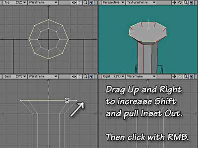
Tap b to get the Bevel tool, and drag up a bit, and right a bit, keeping the shape of the bottom of a sphere in mind as you do.
When it looks right, click the Right Mouse Button (Command+click on a Mac with a one-button mouse.) That accepts the bevel, and sets you up for a new one, in a single step.
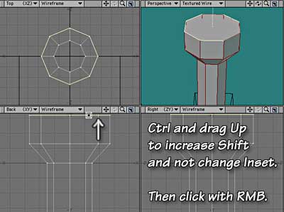
Drag up, to make a bevel that goes straight up (use the Control key if you want to be sure,) for the sides of the knob. Click the RMB again when you think it looks right.
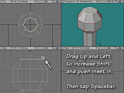
Drag up and to the left to form the top of the sphere. When it looks good to you, tap the spacebar to make the final polys and drop the tool. (Be careful not to click with the RMB before you drop the tool, or you'll have extra geometry that you can't see and don't need, since both click and tap will make new bevels. If you aren't sure you didn't, Undo. If the bevel persists, you had an extra. If it vanishes, you didn't. Tap z to Redo and get it back.)
Beautiful! A pole with a ball on top, in just a few mouse clicks!
We need to rotate the pole until the faces are flat to the axes so we can make the flag easily. To do that, get the Rotate tool from (you guessed it) the Modify tab, Rotate section. (Or tap y.)

A bit of rudimentary math will show that we need to rotate 22.5 degrees. (Since there are 8 sides, we need to move it 1/16 of the way around a full circle to move it halfway through a side. 360 divided by 16 equals 22.5) The trouble is, in interactive mode the tool will only rotate geometry in full degree increments. If we knew exactly where the center of the pole was, we could just type the numbers in; but we don't. We could move it to 0,0,0, but there is an easier way.
Since we are still using Action Center: Selection, we'll use the rotate tool in the Top viewport to let LightWave find the center for us.
Make sure the Numeric Panel is open (n). The numbers should all say 0. Click once in the Top viewport, and you will see the numbers change in the Numeric Options dialog. That's the center of the selection, entered for you, and ready to go.
Now, highlight the Angle field, and input 22.5. Hit Tab or Enter, and the next text field is highlighted. Don't change anything there; just click on the Apply button. The flagpole is rotated 22.5° around its center!
Now we need to select the single poly on the front of the flagpole. We're going to bevel that one poly out to make our flag.
Like the other single poly selections, it easiest to do this in a shaded view. In wireframe views, you can only select a poly by clicking on the edge, and when you do, you select all the polys under the cursor, front and back.
However, it might be difficult to find the correct one in the Perspective view, if you've been moving it around a lot.
So, in the Right view, switch the Rendering Style to Flat Shade by clicking on the second drop down triangle (next to the View Type on the Titlebar.) Then just select the poly that is facing you.
Simple, huh? Switching to a shaded mode prevents you from selecting backfacing polys, and can make selection much easier. Since you can change rendering modes on the fly, in mere moments, it can save a lot of time (and aggravation) to do it that way.
Get the Bevel tool again (b), hold down the ctrl/Control key to constrain movement, and drag straight up in any viewport. Yes, I know, you want the flag to go out to the right; but dragging up always increases Shift, remember? Since the poly is facing down the X axis, shift moves it in that direction. Now do you see what I meant by that?
If you can't make your hand go up when your eyes say to go right, it's okay. It's like rubbing your stomach while patting your head. It just takes practice.
For now, simply undo whatever you don't like, choose Reset from the Actions button at the top of the Numeric Requester to set all the fields there to zero, and type .5 (500 mm) into the Shift field. Tap Enter to accept it, and then drop the tool.
Humm. The flag should really be triangular, shouldn't it? Let's make it so.
Change to Point Selection mode by clicking on the Points button at the bottom of the screen.

Notice that the polygon doesn't look selected any more, even though you didn't drop it. In reality, it is still selected (you can prove it to yourself by going back to Polygon Selection mode for a moment.) When you move from one selection mode to another, the old selections persist. But, since the wrong kind of thing is selected, you can't see them.
Notice, as well, that your cursor is now a cross, not an x. That's a visual reminder of the Selection Mode.
Working in the Top viewport, click on one corner to select both of the points on that side of the flag. The points will light up as tiny yellow squares, and it should read Sel:2 in the Selection Information area.
Click on the Detail tab, go to the Points section, and click on the Weld Average tool button.
The two points become a single point, at the coordinates that are exactly between them.
Repeat for the other side. And there it is! A lovely triangular flag, just like that.
However, making it this way caused the end polygon to be collapsed into a two-point poly. Those can cause various problems, if you don't want them, so let's make it go away.
Tap the spacebar to return to Polygons Selection, and look at the Polygon Statistics panel. (Tap w if it's not visible, to show it.) You can see all kinds of things about your object here. If you look, you'll notice that there's a 1 in the Num column of the 2 Vertices line. That means that you have 1 polygon that has two points (vertices.)
Click the + to the left of it, and you'll select all the polys with 2 Vertices.
Notice that the minus sign is now white, as are the words. Tap the delete key, and the poly will go away. And that's all there is to that.
Let's go to the last page, and we'll finish this model.