Lightwave UV Maps for UV Mapper Users - Lesson 2

This is the second in a five-part series about making the switch from assigning UVs in UV Mapper to using the built-in Lightwave tools. If you haven't at least read the first one, please go back and do so now. It has some important concepts that may not be repeated.

Once again, if you click on any of the pictures, you'll get a full size screen shot.

Render of the finished model. This time, we are going to map a more complex model, so we can take a look at creating an endomorph to aid in defining UVs.

So, if you would like to follow along, download the four-sided die model, D4.sit or D4.zip, and the Texture Maps that go with it, D4Images.sit or D4Images.zip.

This is a shape known well to people who play role-playing games. It's a four sided die; you roll it, and the number that is right side up on the bottom from all directions is the number that you rolled.

Right now, of course, it doesn't have any numbers. We are going to fix that.

Load the model, set up the workspace, and use the D4Color.jpg as the background for the UV Texture viewport. Start a new UV Texture Map. Load the object into Modeler, and set your window up so you have four viewports. Choose UV Texture for the top left Viewport, and load the D4Color.jpg map as the Background. (If you have forgotten how to do all of that, it's explained in the first lesson.)

Start a new UV Map, just like you did for the first lesson. Name it D4_UV.

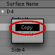
Assign the map to the color channel of all 4 materials. Now, so that we can see the map on the model while we make it, open the Surface Editor, and assign this map to the four named surfaces of the die. (Don't forget that you can click on a surface with the Right Mouse Button, copy it, and paste all the attributes to the next surface.)

If you don't know how to assign a UV Map to an object, please see Lesson 1.

The die will turn blue, which is the background color of this map; but you won't be able to see any numbers on it. We still have to do that part.

Select the Side3 surface using the Polygon Statistic window. Choose the Side3 surface polys by opening the Polygon Statistic window (w on the keyboard, or choose the Modeler button on the toolbar, and then Windows > Statistics Open/Close,) scrolling down to Surf:name, choosing Side3 from the drop down menu, and clicking the + (plus sign) to select all seven polys in the surface. This is equivalent to Select > by Material in UV Mapper.
You can see this surface is square to the Y axis. As you can see, this is the bottom of the die, and it's square to the Y axis. So, to map it, all you have to do is go to the Map tab, then Texture > Make UVs. This is the same as choosing “Make new UV map” in UV Mapper, remember.
In the Assign UV Coordinates requester, pick Planar, Y, Automatic. The Assign UV Coordinates requester will open, allowing you to pick the Map Type, Axis, etc. Pick Planar for the Map Type, Y axis, and Automatic. It's easier to pick the correct axis here than in UV Mapper, because you can easily see which one is perpendicular to the surface.
Flip the UV Map, so the numbers aren't reversed. The new UVs will show up on the map, sized to fill the whole square.

Cut the polys using the keyboard, and paste them right back in. This will unweld the points, so the polys that make up this surface can be manipulated separately from the polys that make the other surfaces. Select the surface once more.

Now we have to place the polys in the correct position on the map. Since this is a die, the numbers have to be in exactly the right places. To make sure that they are, set one of your viewports to Bottom, Texture mode. You will be able to see the numbers on your die when you do this.

You will notice that the numbers are backwards; that is, they are mirror images of what they should be.

To fix them, of course, you need to go to Map > Texture > Flip UV Point Map. When the requester appears, Flip U. (Remember, U flips right to left, V flips top to bottom.) Presto! The numbers are in the correct orientation. (You can also see, since this map isn't symmetrical, that Flip UV Point Map really does flip the map.)

Manipulate the polys on the map so that the 4 is on the left hand side in the "Bottom" viewport. Working on the map, use the Size and Rotate tools to line the triangle up with the image of the die in the middle. (Each numbered side corresponds to the part of the image that doesn't have that number on it. So, Side3 will be in the triangle that contains 1,2, and 4.) Manipulate the triangle until the numbers are roughly in the same positions that they occupy in the picture here.

Don't use the Numeric window when you do this. It only affects the model, not the map, and that's not what we want.

Drag the points to align the poly with the map image. The triangle doesn't fit very well, does it?

Here is another advantage to using the built in Lightwave tools. You can use the Drag tool to put the points exactly where you want them. Get it, by hitting Control+t/ctrl+t, and drag the points on the map until the triangle lines up with the one on the image. Is that easy, or what?

Make a new Endomorph. (M > New) But wait, it gets better. Drop this selection, and select the Side2 Surface. As you can see, this isn't perpendicular to any axis. In UV Mapper, we would rotate the model to map this side.

Here, we will do the same thing. But, so that we won't run any risk of messing up the model while we do so, we will rotate an endomorph, and not the base model.

To do that, we first have to make the endomorph. So, go to the M at the bottom, and choose (new) from the menu there, (or Map > Morph > New Endomorph.)

Name it "Mapping." Name the Endomorph something like Mapping, so you don't get it confused with any other endomorphs that you might have.
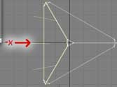
Note the selection, then drop it, and rotate the model so those polys are square to the X axis. Check the top view to see which side Side2 is, and then drop the selection, and rotate the model so that side is perpendicular to the X axis. See the advantage? You can see the rotation while you do it!
Make UVs: Planar, X axis. Select Side2 again, and Make UVs, just as you've done before. This time, of course, choose the X axis.
Position the polys on the map so the 3 is at the bottom. Cut and paste, reselect, take a look, flip the UV Point Map if necessary, and resize as before. Move the polys to the lower left triangle on the Color map.

Rotate so that the number 3 on the die is against the Side3 face that you have already done. (Otherwise, the poor gamers won't have any idea what number they have rolled.) Drag the points into place again, and drop the selection.

Rotate the Side1 surface until it's completely square to the X axis. We are going to do the third side a little differently. Make sure that you are working in the Mapping endomorph, and then select the Side1 surface.

This time, cut and paste it right away, and then select it again.

Using the Rotate tool, rotate the polygons in the model until they are perpendicular to the X axis in the top view, and then until they are perpendicular to the X axis in the Back view as well.

Yes, the model will come apart; but that doesn't matter, because you are working in an endomorph. You can pull the model to pieces here, if it will make it easier to map, and the base model will remain intact, with nothing added but the UVs.

Position the polys on the top triangle on the map, with "3" at the bottom. Make UVs once more, and then, working on the map, shrink and slide the new polys into the 2,3,4 triangle at the top. (This time, you won't have to rotate it at all!)

Drag the points on the map into alignment, if necessary.

Check, to make sure that the number 3 is against the Side3 that we have already done, and that the number 2 is against Side2. (If you can't tell from here, switch back to the (base) endomorph. Just be sure to switch back here when you've checked.)

Select Side4; then cut, paste, Make UVs, and drag the points into place. Finally, choose the Side4 surface.

We are going to use the Lazy Artist method on this one. (Or perhaps, the Efficient Artist.)

Cut and paste, reselect, and then, without any further manipulation, Make UVs (look at the viewports to decide which axis would make the best ones.) Resize and rotate, as usual, and make sure that the numbers line up with the correct sides. (2 with Side2, 3 with Side3, etc.) Then just drag the points to where they need to be. As you can see, when it's this easy to put the points where you need them, you can be a little sloppy with the rotation.

Change the surface of the whole die to BlueD4. This leaves just the corners; and they haven't been assigned to any material. This might be a problem in UV Mapper; but in Lightwave it's nothing. In fact, it's no longer really necessary to have four different materials in this die; they all use the same map after all.

So, make sure nothing is selected, hit q to get the Change Surface requester, and change them all to a new surface; call it BlueD4. Open the Surface Editor, and paste the mapping in. (It should still be in your surface copy/paste buffer, unless you have quit Lightwave since you started this lesson.) That will save you all kinds of time later, since there is now only one surface to change.

The corners are all blue now; but just to be tidy, lets assign them to places on the map, too. Select one on the model, tap the ] (right square bracket) key to select all connected polys, and MakeUVs to add them to the map. I'll leave the rest of that up to you; it's good practice, and you can't go wrong.

Go to Modeler > Windows > Vertex Maps Open/Close. Now, if you remember, you will need to merge the points to make it all one piece again. But, in order to do that, you'll have to dispose of the endomorph. (Points that are not in the same place on the endomorph won't be merged.)

So, go to Modeler > Windows > Vertex Maps Open/Close.

Choose Morph > Mapping > Delete Vertex Map. Then hit m to merge points. Open the Morph menu, choose the Mapping endomorph you made, and then use the Right Mouse Button (or Command + Click on a Mac with a one-button mouse) to get the contextual menu.

Choose Delete Vertex Map, and it's gone. (This is the same place that you delete, rename, or copy Texture Maps too, by the way, in case you want to do any of that.)

To finish up, tap the m key to merge all the points, making the model one part again. (You should have 24 points eliminated.)

And that's it! You can add the bump map, if you want to, so you can use this die. After all, it's ancient and venerable. To get the image for this map, I scanned in the very first D4 I ever purchased for D&D, way back in 1977. (This was long before AD&D.) Enjoy it!

Okay! You know how to Map UVs, and how to use an endomorph to make mapping easier. If you would like to, you can go to Lesson 3, where we'll see how to do a model that uses two maps, and practice some more complex endomorph mapping.

If you have a question, write to me and ask it!

Everything on this site is copyright © Robin Wood; all rights reserved. Please do not use anything without permission. To get permission, write to Robin, and explain what you intend to use it for.