Lightwave UV Maps for UV Mapper Users - Lesson 1 Page 2

This is the second page of this tutorial. If you haven't finished the first page, you can find it here.
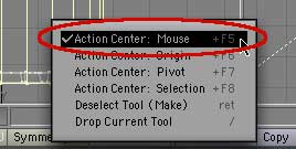
Set Mode (at the bottom) to Action Center : Mouse Get the Stretch tool (h on the keyboard, or Modify > Stretch > Stretch) and make sure that the mode is set to Action Center: Mouse. (It's at the bottom of the screen, in the middle.) Hold down Control/ctrl to constrain the movement to a single axis, put your cursor on the bottom of the map, and pull down.
Picture of corner stretching.

But wait! One of the corners is stuck to the corner of the map! Why?

It's because of the "no point can be in two places on the map" thing. If you look, there isn't a point at all on that corner. The point for that poly is on the right side of the map. Without a point to move, all the vertex can do is stretch. We need to fix that right away!

Undo, so the polys cover the whole map, and we'll try this again.

(By the way, I darkened the map on the illo, so you can see the polys.)

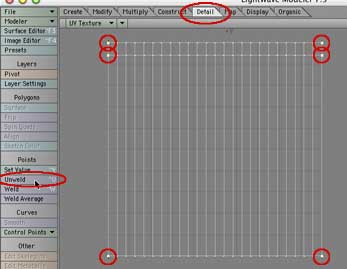
Select the points on the right edge. Working on the map itself, select the all the points on the right edge.

(It's easiest to do this by holding down the Right Mouse Button (RMB) to get the lasso, and drawing around the edge. Don't draw "the hard way" between the polys. Start just to the left of the first point, make a big loop to the right, and end just to the left of the bottom point. The lasso will "snap" from one end to the other, and select all the points.)

Go to Detail > Points > Unweld Points to get points on all the edge vertices. Then tap Shift+Control+u on a Mac, or shift+ctrl+u for a PC (or go to Detail > Points > Unweld.) As soon as you do, you will notice that points appear on the left side of the map.
Shrink the polys until the edge is on the green/purple line. Select the can polys, get the Stretch tool, hold the Control/ctrl key, and pull the vertices down again.

This time, they move easily. Remember this.

Drag them down until the line between the two sets of polys just meets the green/purple interface. As you do, you will see the label sliding up the can, until it's just where it should be. (If you have a hard time getting it exactly right, zoom in and try again. Lightwave seems to have a snap which is dependent on screen size.)

Select the Lid polys, make a planar map using the Y axis. That was easy! Drop this selection, and select the lid of the model by clicking anywhere on it and selecting the connected polys (]) once more.

Go to Map > Texture > Make UVs, and we'll map the top. This time, of course, choose Planar for the Map Type. Once again, you'll want the Y axis because it's perpendicular to the surface you want to map, as you can see by looking in any viewport.

Use the Size tool (H) to shrink the polys on the map, and the move tool (t) to drag them into place. When you click OK, the polys will fill the map, and the image will appear on the top of the can. You need to shrink and move it.

Use the Size tool this time (Shift+H, or Modify > Stretch > Size) so it will stay round. (This will depend on the dimensions of the map, of course. But I made this one, and happen to know that it's square, and those circles really are circles.) Shrink it, and then use the Move tool (t, or Modify > Move > Move) to drag it into place. Tweak if necessary. You will probably want to leave some purple rim around the polys. You can check to see if you've left enough by looking at the texture on the model. (If it's too blurry to see, you can increase the resolution. Just type d to open the Display Options, and change the Texture Resolution under the Layout tab.)

Repeat for bottom; but the type is reversed. When you are happy with it, select the bottom polys, and map them exactly the same way.

As soon as you do, you will see the label on the bottom, as usual.

But wait a minute! The words here are reversed!

Go to Map > Texture > Flip UV Point Map No problem. Here's another advantage of using Lightwave.

Go to Map >Texture > Flip UV Point Map. (Don't be confused by Flip UVs (Per Poly.) It'll flip them alright, but on the model, not the map.)

When you click on the button, a requester will open, allowing you to choose to flip on the U axis, the V axis, or both. U will flip the right side for the left. V will flip the top for the bottom, and both, of course, will flip both. In this case, we need to Flip U.

Do that, and you will see the words suddenly are right way round again!

Open Display Options > Backdrop and click Invert to see the polys easily. We need to put the polys in place on the map, but you may find it hard to manipulate the yellow polys on the white texture.

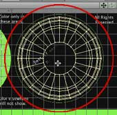
If you do, you can fix it easily. Open the Display Options again (d,) go to the Backdrop tab, to the TL viewport, and click the Invert button. The polys are much easier to see against the black, aren't they? (You can also decrease the Contrast and / or the Brightness, of course, if that makes it easier. I find this is quicker for some things.)

Resize and position the bottom polys on the map. Shrink the map for the can bottom, exactly like we did for the lid, and place it within the white circle on the right.

As you can see, the words look fine on the bottom of the model.

Use Construct > Subdivide > Bandsaw to select vertical lid polys for mapping. The model is now mapped, and it looks good. “But wait!” I can hear you saying, “When UV Mapper maps with the Cylindrical Caps method, you get all the vertical polys mapped on the cylinder, and the horizontal polys mapped as the cap. This way, some of the vertical polys are mapped wrong; the map will stretch!”

Yeah, but in this case it doesn't matter, since there is nothing there but flat color; even the bump map doesn't address them.

You don't care? Picky, picky! :)

Alright. In the Perspective view, click on two adjacent polys on the vertical portion of the lid. Then go to Construct > Subdivide > Bandsaw. When the requester opens, leave it all set to the defaults, and click OK.

Lightwave will select all the four sided polys in that direction. In this case, all the polys around that rim. Cut the whole section, and paste it back in to get the points for the map, again.

Map (cylindrical Y,) unweld the side points, and place the polys on the map. Select them all again, and then just Make UVs. (Map > Texture > Make UVs.)

(Don't forget to unweld the seam before you try to resize.)

Repeat for any others that you are concerned about. (You have to use the Bandsaw on one set at a time; but you can copy, paste, and map all of the remaining ones at once, if you want to.) Just like UV Mapper, if you change your mind about the mapping method, Lightwave will collect the polys from wherever they are, and remap them without batting an eye.

Replace the SwoopCanColor.jpg with SwoopCanBump.jpg to adjust the bump map. Okay, now let's look at another one of the advantages of using Lightwave for your UV mapping needs. Load SwoopCanBump.jpg as the image in the TL viewport. Use it as the image for the Texture in the Surface Editor, too, so you can see what you are doing.

As you can see, the logo on the top is exactly square to the front of the label. That won't look very realistic! Let's change it.

Select the lid polys on the map, and then rotate them to rotate the bump for the lid. Change the Mode to Action Center: Selection, so you won't lose the careful centering of the lid, select the lid polys right on the map, and get the Rotate tool. (y, or Modify > Rotate > Rotate.)

Place the tool in the middle of the lid, and rotate! As you do, you will see the logo rotate on the model lid. Stop when you are happy with the placement.

Finally, type m to merge the points in the model. Now return the Texture Image to SwoopCanColor.jpg, and use SwoopCanBump.jpg in the bump channel.

As a final step, make sure nothing is selected, and then merge all the points again by simply tapping the m key on the keyboard. Leave the requester at the default, and all the bits you copied, pasted, and unwelded will be reunited into one seamless whole.

The can is all mapped, and ready to go!

If you were planning to use this model in Lightwave, you're set. But if you wanted to export it as an .obj file, you can still do that, too. Just make sure that the map is being used in at least one channel when you export it, and the UVs will stick. (Color channel is best, since some programs ignore the other channels.)

So much for simple stuff. Continue to Lesson 2, if you want to see how to rotate the model so you can map from any angle.

If you have a question, write to me and ask it!

Everything on this site is copyright © Robin Wood; all rights reserved. Please do not use anything without permission. To get permission, write to Robin, and explain what you intend to use it for.