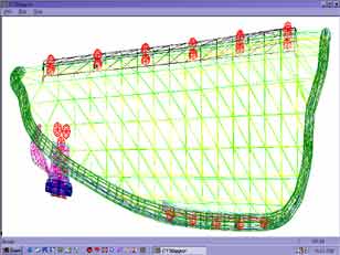
Let's take a look. FIrst, of course, you open the program and load your new model. You may get one of several things at that point. If it has a beautiful UV Map already made, and you don't want to change it at all, go to the end of this tutorial and save the map. You may get a tangle of lines, or UV Mapper may tell you that some of the Data is Out of Bounds. Or, if there is no map at all, you will get the notice above on a blank screen. In all cases except the first one, you probably want to make a new map.

So, you have created (or downloaded) a lovely mesh; but you need to put UV coordinates on it, so it can read a texture map. You have downloaded UV Mapper (Thank you forever Steve Cox!) but you have no idea how to use it.
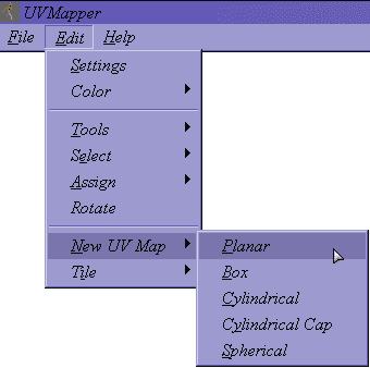
Go to the Edit menu, choose New UV Map and then choose Planar from the fly out menu. This is the easiest kind of map to see, since it just shows your model from one side or another, depending on the axis you choose.
X-Axis will be the same as choosing the Right or Left view in Poser. Y-Axis will be the same as the Top or Bottom view. Z-Axis will be the same as the Front or Back view. You can also choose whether the object will be split, and how, and how the two halves will be arranged. (Split by... and Orientation.) Don't Split the model at this point; we want just one piece for now. Leave Gaps in Map checked, although it doesn't apply at the moment, and leave Scale Result unchecked. (If you enable Scale Result, the program will scale each piece; but I find that I always have to resize them after it does. For me, it's just easier to eyeball the proportions when I'm putting the final map together. If that's difficult for you, by all means check Scale Result.) Hit OK, and you will see a wireframe of the model, filling your screen.

This dialog box will open, that will allow you to choose the axis that you want to view your model from. If you are familiar with the program Poser, it you can tell pretty easily where in space you are.
So, go to the Edit menu again, and choose Color > By Material.
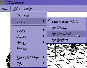
By default, the map will be in black and white. It's easier to see what is going on if you choose to view it in color, however.
Make it tiny, and then drag it down into the lower right hand corner so it's out of the way.

In any case, we need room to work, and this model is way, way to large. Hit Ctrl+A to select the whole thing, and then tap the / (backslash) key a few times. Each time you tap it, the map becomes one quarter the size it was.
So, go to the Edit menu, and choose Select > By Material. (If you didn't have materials, and you are using Groups, or Regions, you would select by those, of course.)

We are going to pull one Material at a time from the model, and arrange it so that it will be easy to paint in a graphics program.
I usually choose the one that is the most important. In this case, that's Leather_Outer, because it is the outside of the vambrace, where the tooling will go in the finished model.

A dialog box will open that has a list of all the materials in your model. Choose whichever material you want to start with.
Take a look at it. Can you see all (or most) of the area? Or would it be better if the map was applied differently.

The material you have chosen will be highlighted in dark red. Place your cursor on it, and drag it away from the rest of the map, into the center of the screen.
Planar just looks from one side or another. Box assigns all the polygons to one of six sides, depending on how they are facing. It's great for boxes or other regularly shaped things; but can be very confusing to paint on more organic forms, especially when you are just beginning to understand the program. (As you become more adept, you can drag the facets around and get a lot of use out of it; but it is still pretty time consuming.) Cylindrical unwraps the facets, so that you can paint a map and then wrap it back around. It's great for things that you could slide into a tube. Cylindrical Cap is like Cylindrical, but also assigns any facets that are pointing at right angles to the cylinder to a cap. This keeps you from having to stretch the top and bottom of things that have tops and bottoms. Spherical unwraps the facets in the form of a sphere, of course. You would use it for things that would be more comfortable in a ball than in a tube. Since the Leather_Outer material is roughly the same shape as a sleeve, it will go nicely in a tube and doesn't need the ends. So I'm choosing Cylindrical Mapping. Go to the Edit menu, choose New UV Map, and then the type of map you want to use from the fly out menu.

There are several mapping modes to choose from.
Since I chose Cylindrical, I got a dialog that's a little different than the Planar dialog, as you can see. This is the one that is used for Cylindrical, Cylindrical Capped, and Spherical. Alignment, of course, let you choose which axis you are wrapping the map around. If you want the map to wrap around the vertical axis, for instance if you were mapping a soda can that is standing upright, you would choose Y-Axis. If you want to wrap the map around the axis you are looking down as you look at your model from the front in a program like Poser, you would choose the Z-Axis. If you want to wrap the map around the axis you are looking at the side of when you look at your model from the front in Poser, you would choose the X-axis. (Since we chose to map the first Planar map from the Z-Axis, it makes this choice easy. If you are looking down the tube, choose the Z-Axis. If you are looking at the side of a tube that's lying down, choose the X-Axis. If you are looking at the side of a tube standing up, choose the Y-Axis.) If you want the seam of the cylinder to start in a different place, you can do that with Rotation. The seam will be at the bottom of the model if you are using the X- or Z-axis, and at the back if you are using the Y-axis. This is generally where you want it. (I'll be talking more about Rotation in a bit, if you need it.) Offset lets you wrap the cylinder around a different center point. UV Mapper calculates the center point by looking at the edges of a bounding box that surrounds the center, and taking the point in the exact middle. (The Min and Max for each axis.) If you know that the middle of you model isn't in the center of its bounding box, you can offset that point here. There is no easy way that I know of to calculate the offset, but you can get a starting point by going to the Help menu, and choosing Dimensions. A dialog will open that tells you the Min and Max values, which will give you a starting point. Fortunately, you won't need this often. (If you choose your material wisely, you may never need it.) In this case, I need to wrap the map around the X-axis, so I chose that.

When you choose it, a dialog box will open that allows you to parameters for that Mapping mode.
If you get something like this for a Cylindrical Map,
Just choose a different axis, and try again.


If you choose wrong, though, it's easy to tell and easy to fix. If you map looks like this one, just choose another axis.
As you finish each one, move it to the edge of your screen, out of the way, so you have room to work. Leave them all small, for now. If you need to make any pieces larger to work with, go ahead. (You can quadruple the size with the * (asterisk) key.) Just make them smaller, and shove them out of the way, when you are finished. Be sure to save often as you go. Don't save the map; just the model. You can always load it again if you have to, and the map will be there just like this. (Don't worry about the settings for now, either.)

Continue to select each piece, determine the best mapping mode for it, and make a new map.
You can fix this pretty easily.

Occasionally, as you work, you will come across a bit that is not lying square to the Axis. If you map it like that, you will build distortions into your map, which are better to avoid.

Go to the Edit menu, and choose Rotate, to rotate the model. (Not the map. You will have to make a new map to see the rotation.)
There is no visual feedback; nothing to let you know when you are where you want to be. But, if you have Poser, (or a similar program,) there is a workaround. Just load your model there, go to one of the orthogonal views (Front, Back, Top, Right, etc.) and rotate your model until it looks right. Then, copy the numbers for the degrees of rotation into these boxes.

A dialog box will open that allows you to set the rotation you desire, in whole degrees. (No fractions here.)

That's all there is to it. If you make a new map of the same type now, you will be able to see the rotation.

Then choose the mapping method you need, and go ahead and make the new map, of whatever kind you need. (This is Planar using the Y axis.) The model will retain these rotation values until you change them. (So, if you need the whole thing rotated, you can do it, and still remap each part as you need it. Or, if you need to rotate it this way and that as you go, you can do that, too.)
I need Planar projection from the Y axis for the strap around the arm, so I can tool it. But I would rather use Cylindrical Mapping for the wrist band. Once again, it's not difficult. Select the material, and make the first map. Tap the Enter key, or click in any empty area, to drop the selection.

Occasionally, you may find that you want to use two mapping modes on two parts of a single material. For instance, the straps for my vambrace.

Then drag a marquee around the area that you want to map using the second method.

Now make the second map. If you don't have Scale Result enabled, the new map will exactly fill the selection box you dragged out. (See why you need space to work.)
All you have to do is select the vertices that you want to move, and drag them to the new position. You can use the arrow keys on your keyboard to nudge them in 1 pixel increments (or shift+arrow to nudge them by more,) so it's easy to do. That's all there is to it. When you select it now, it will all act like a single thing. In fact, you can put stuff that should belong with one material with another this way, and combine them both in the same map if you are so inclined. You can do pretty complex things using these methods alone or in combination. For instance, you can cut the sleeves off a shirt by pulling the facets that make the sleeves to one side, and piling them all up on each other any old way. Then, select the whole batch by drawing a marquee around it, and make a new Cylindrical map. UV Mapper will straighten them all out, and give you a lovely sleeve.

Sometimes, you will want to take vertices from one part of the map, and move them to another. I'll show you that using the same wrist band. (I have to mention here that for this it would be easier to just change the Rotation in the UV Mapping dialog to 180°, so the seam would be at the top. But for purposes of illustration...)
Just grab any of the control handles, and drag to resize. Or, if you prefer, you can make your selection (and the vertices in it) larger on the X (horizontal) axis by tapping the x key. Shift+x makes it smaller. If you want to resize it on the Y (vertical) axis, use the Y key. If you want to make finer adjustments, use the U and V keys the same way.
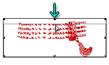
As you can see, the proportions for the wristband are all wrong now. But, once more, it's easy to fix.
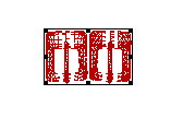
If you decide that you want a map for each side of the piece you are working on, like this belt buckle, you can easily split the map if you are using Planar Mapping.
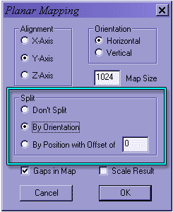
Just choose the kind of split you want in the dialog that opens when you make a new map.
When it splits the map, it takes all vertices that are facing one direction, and puts them on one side of the map. All vertices facing the other are put on the other half. So, depending on how the normals lie in your model, you may find your map cuts the model exactly in half, or you may find that nearly all the vertices are on one side or the other. Splitting by Position simply cuts it in half along the center of the axis. Offset lets you offset where the center is, of course. Once again, you can get a hint from checking Help > Dimensions; but it's not easy to figure out.
Split Orientation -
Which way are the vertices facing?Split Position -
Where are the vertices?


Splitting it by orientation will split along the axis you are using for the map. That is, it would split into the top and the bottom if you were using the Y-Axis, the left and right using the X-Axis, and the front and back using the Z-axis. (Once again, taking the orientation as you would look at your model from the front in Poser.)
In all cases, I highly recommend that you choose to leave gaps in the map. If you don't, sometimes a vertex will be caught between the two halves, which can make it difficult to paint later.
Vertical Orientation
Horizontal Orientation


In addition, you can choose to have UV Mapper place the new map so the two halves are arranged vertically, or so that they are arranged horizontally. Just check the one you want in the Orientation checkbox at the upper right corner of the Planar Mapping dialog.

You should already have saved the model several times, just in case, so you should be familiar with that save dialog. Generally, you can leave the defaults just the way they are; but do check Don't Export Linefeeds if you want your friends with Macs to be able to read the model. (This won't affect the ability of PCs to read it, as far as I can tell.)
If you were using a background map, you will want to use that size (or at least those proportions.) For other things, you will probably need to experiment a little. Export a map, Select All in Photoshop, and size that selection until it looks right. Then copy and paste it to a new document. The size of that document is the size you want for your proportions. In my case, using a (virtual) monitor size of 1024 x 768, I have found that saving the Texture at 1024 x 662 gives me the same proportions as a Maximized screen.

Before you save the Texture Map, you need to go to Edit Settings. If you don't, you are very likely to wind up with proportions that are nothing like the ones you see on the screen. Set the dimensions, in pixels, of the texture map that you want to output.
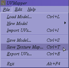
Save the Texture, and you are ready to go into your favorite graphics program, and paint your map!

I do recommend that you check it out before you actually spend any time painting it. Import it into a program where you can render it, apply the map just as it is, and render from a few angles to make sure all is as it should be.
You can either fix that in UV Mapper by rotating the object and trying again, or you can just flip the part in your graphics program, so the type looks reversed in the map, but shows correctly on the model. Once you are sure that all the parts are present and accounted for, and everything is facing a predictable way, you can start to paint your texture. Have fun!

If the finished texture will have any parts that cannot be viewed backwards, such as writing, I recommend that you put numbers or letters on the parts and render before you spend time painting. Depending on how your model was situated in UV Mapper's memory, you may find that some surfaces are back-to-front, which has the effect of reversing your type, since you are actually looking at the back of the vertices in the map.
